 |
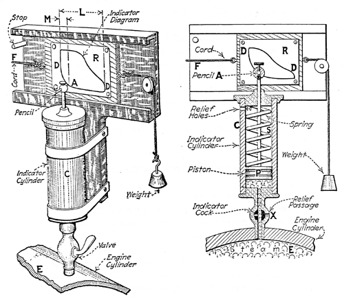
The instrument shown in the Croft drawing consists of a vertical tube C — approximately 10in high with a diameter of 1.125in — attached to an iron or wood frame D at the top and a steam cock B at the base. The pipe was usually designed to mate with the grease cock on the cylinder cap of the engine A, but could also sometimes be fitted to the lower end of the cylinder to check the valve settings. The tube contained a tight-fitting piston F with a hollow tail rod extending upward through the top cap. A short transverse brass tube, containing a light spiral spring and a pencil or pencil or 'crayon' L was fixed to the tail rod to serve as an indicating pointer. A large spiral spring S was contained within the body C, surrounding the piston rod. The spring was anchored in the back of the piston head P and either in a bracket on the supporting frame or in the top-cap of the tube, so that it was capable of a limited amount of compression (to register the low maximum pressures of the Watt beam engines) or a larger degree of extension to register the vacuum created in the condenser. Steam was admitted from the engine cylinder E through the indicator cock X into the indicator cylinder C. The pencil A traced its linear diagram D R D onto a sheet of paper, pinned or clamped in place, as the tablet slid along the under-edge of its supporting frame. A cord F attached to the tablet was led around a small pulley on the frame to a suitable moving point on the engine — on the parallel motion, for example — which moved no greater than the six inches required for the diagram. The return stroke of the tablet was undertaken with the help of a weight suspended from another cord running over a pulley on the opposite side of the indicator frame to complete the diagram.